Create a communication framework
Translate an appearance image into views and questions that design, engineering, and suppliers can discuss.

ARK AI DESIGN SKILL · AI product drawing generator
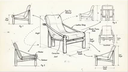
Extract visible form, proportion, components, and materials into multi-view, exploded, detail, and annotation directions so design and manufacturing teams can identify what needs to be developed.
The demo could not be loaded. The preview and page remain available.
Capability
An AI product drawing generator reorganizes visible silhouette, proportion, components, material, and connection clues from one or more product images into front and side views, detail enlargements, exploded ideas, and technical annotations. Its value is to make unknowns visible and help designers, engineers, and suppliers start a structured conversation.
A photograph does not contain verified dimensions, internal construction, wall thickness, joints, tolerances, material grades, load cases, or safety information. The AI may infer or invent all of them. The output is only a secondary-development brief and must never be used directly for quotation approval, tooling, cutting, machining, assembly, certification, or production.
Translate an appearance image into views and questions that design, engineering, and suppliers can discuss.
Use callouts and exploded ideas to identify joints, transitions, and material decisions.
When only images remain, establish a measurement, modeling, and verification checklist.
Place appearance, material, and structural hypotheses together and mark what is known.
Prepare the input
Clear source material and an explicit design objective give the model better evidence to work from. Use these checks before generation.
Front, side, rear, underside, and detail images reduce speculation about hidden construction.
Provide at least one trusted dimension or physical reference; all generated dimensions remain unverified.
Explain whether the product uses timber, metal, upholstery, plastic, or composite construction.
Use CAD, 3D, BOM, material, and test records as the source for formal development.
How to use
Keep the first pass exploratory, compare alternatives, then carry the selected direction into the rest of the project.

Use clear images of the same product version with visible silhouette and detail. Prepare these inputs: Upload product image. Include optional inputs when needed.
Set Drawing type, Dimensions (mm, optional), Image Ratio for this task, then confirm before generating.
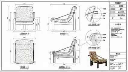
Treat every automatic dimension and hidden detail as a question until verified. Use measurement, CAD, prototypes, standards, and review to create approved drawings and BOM.
Official skill demo
This example is published for this exact skill. It is shown as one complete official reference, not as an independently verified input/output pair or a promised result for your upload.
What the AI reads
The model can infer visible form, edge, material, and part relationships from pixels. It cannot read internal construction, dimensions, tolerance, load, or material performance.
Never send generated output directly for tooling, cutting, purchasing, machining, or assembly. Qualified design and engineering teams must create, check, approve, and control all production documents.
Practical guidance
Label measured, documented, inferred, and unknown information so a supplier cannot misread the board.
Ask about joint type, wall thickness, material grade, tolerance, and assembly instead of allowing invented detail.
Confirm that all photographs and dimensions describe the same revision.
Design, engineering, process, quality, and supply teams should sign off production files.
Where it helps
Translate a visual concept into a page of development questions.
Explain appearance and unresolved details before formal quotation or sampling.
Create a task list for measuring, modeling, and rebuilding missing records.
Discuss appearance, material, parts, and structural assumptions together.
Workflow comparison
AI organizes visible information. Professional engineering drawings define controlled geometry, material, joints, tolerances, performance, and responsibility.
| Decision point | AI Product Drawing Generator | Conventional workflow |
|---|---|---|
| Data source | Infers from images and limited text | Uses measurement, CAD, calculations, prototypes, and standards |
| Creation speed | Rapidly arranges views and annotation ideas | Models, calculates, dimensions, checks, and releases each item |
| Engineering reliability | Every dimension and structure needs validation | Creates controlled data inside an approval system |
| Permitted use | Briefs, questions, and early discussion | Sampling, tooling, purchasing, manufacturing, and quality |
The safe use of AI is to surface engineering questions earlier, never to bypass engineering. Any data entering production must be rebuilt and approved.
FAQ
No. Automatic dimensions do not have a trusted measurement source. Use physical measurement, CAD, or controlled model data.
No. It lacks verified structure, tolerance, materials, BOM, standards, and approval and could create quality or safety risk.
They reduce some visual ambiguity but cannot recover internal construction or verified data.
Use it for early briefs, detail discussions, measurement checklists, and development planning—not production release.
Ark AI
Start with real project material, compare a few directions, and keep developing the selected result in the Ark AI canvas.